Design A Combinational Circuit That Generates Output As 1

1 Bit Comparator Logic Electronics Circuit Bits

Combinational Logic Logic Electronic Engineering Circuit
Https Ece Uwaterloo Ca Msachdev Ece223 Assignment4 Solution 3rd Edition Pdf

3 Bit Synchronous Up Down Counter Electronics Circuit Counter Circuit
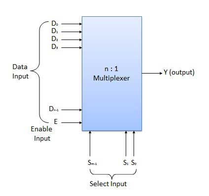
Combinational Circuits Tutorialspoint
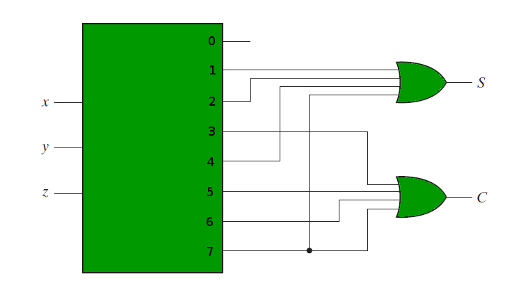
Combinational Circuits Using Decoder Geeksforgeeks

Design a combinational logic circuit with three input variables such that it will produce logic 1 output when one or two the input variables are logic 1 but not all the three.
Design a combinational circuit that generates output as 1.

What Is A Sequential Circuit Digital Electronics Electronics Area Circuit Digital Electronics
Http Web4 Uwindsor Ca Users A Alginahi 60 265 Nsf 831fc2c71873e46285256d6e006c367a 9391445fba4fc83f85256fc8004827a3 File Assignment3 Solutions 20265 Pdf

Sequential Logic Circuits Circuit Digital Circuit Logic

4 1 Annotated Slides 4 Combinational Logic Computation Structures Electrical Engineering And Computer Science Mit Opencourseware
Source : pinterest.com
