A combinational circuit can have an n number of inputs and m number of outputs.
Design a combinational circuit with three inputs and three outputs.
When the binary input is 0 1 2 or 3 the binary output is two greater than the input.
Y should be true if the number is prime.
When the binary input is 0 1 2 or 3 the binary output is one greater than the input.
When the binary input is 0 1 2 or 3 the binary output is one greater than the input.
When the binary input formed from xyz is 0 1 2 or 3 the binary output produced by abc is.
Specifically x should be true if the number is divisible by 3.
Design a circuit that has a 3 bit binary input and a single output that output 1 if it is a prime number.
Design a combinational circuit with three inputs x y z and three outputs a b and c.
When the binary input is 4 5 6 or 7 the binary output is one less than the input.
Design a combinational logic circuit with three input variables such that it will produce logic 1 output when one or two the input variables are logic 1 but not all the three.
The half adder circuit is designed to add two single bit binary number a and b.
Eg 2 10 3 10 5 10 7 10.
And z should be true if the number is a.
Example of combinational logic circuit.
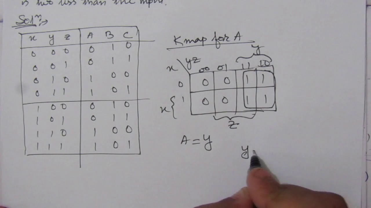
Design a combinational circuit with three inputs x y and z and three outputs a b and c.
Compare two 1 bit numbers.
Design a combinational circuit with three inputs x y and z and three outputs a b and c.
Follow the above listed points to design the logic diagram as per the given statement.
We re going to elaborate few important combinational circuits as follows.
When the binary input is 4 5 6 or 7 the binary output is one less than the input.
And three outputs x y z.
Design a combinational circuit with three inputs x y and z and the three outputs a b and c.
When the binary input is 0 1 2 or 3 the binary out.
When the binary input is 0 1 2 or 3 the binary output is 1 greater than the input.
The inputs represent a binary number in the range 0 15 and the outputs represent characteristics of the numbers.
Half adder is a combinational logic circuit with two inputs and two outputs.
When the binary input is 4 5 6 or 7 the binary output is one less than the input.
4 5 design a combinational circuit with three inputs x y and z and three outputs a b and c.
Given two input bits a and b produce three outputs x y and z so that x is 1 only when only when a b y is 1 only when a b and z is 1 only when a b learn more.